In the first installment of this project car series, hardcore track enthusiast and project car owner Steven Tory found the source of the “bits in his oil,” but only after a complete engine teardown on his 1995 993 C2.
As it turned out, the “bits” were pieces of the engine’s intermediate shaft (IMS) thrust bearing that had literally just started to break up inside his engine prior to his “well-timed” oil draining. Only four small pieces of shrapnel were found, and the main pieces of the IMS thrust bearing were still in place. Fortunately the rest of his engine was completely unscathed by the ordeal, judging by a thorough inspection after the teardown. The IMS thrust bearing is not an identified trouble issue on air-cooled flat sixes, unlike the IMS issues on Porsche M96 water pumpers, which are well known, so Steven definitely had the good car Gods looking out for him that day.
Now the real fun can begin—with engine rebuild planning and full clean-up at the top of Steven’s “To-Do” list.

Steven was up to the technical task himself (with a little assistance and encouragement from yours truly), and really had four choices on how to go about the repair of his fully disassembled 3.6L Porsche flat six. The first choice was the simplest: He could do an extremely thorough clean-up, renew the two IMS thrust bearing halves, swap out all “known must replace” parts, and put everything back as he found it. His engine was strong and performing perfectly prior to the “incident,” but the process and man hours of disassembly and assembly would be the same as the option number two.
The second choice was he could undertake a complete OEM rebuild, which would include the measurement of all technical clearances (bearings, pistons, rings, etc.), and replacement of any out-of-spec or damaged parts as necessary with the OEM pieces. Several hours of extra time is required for such measurements and determining what else should be replaced. However, the advantage of this could be time and money very well spent, because the engine was already fully opened for such an evaluation and may very likely reveal another inexpensive (or expensive, it does not really matter which) part that might be ready to let go.
The third option was a mild performance rebuild along with additional head work to RS spec and an increase in displacement.

The fourth and final option was the “enthusiast’s choice”: He could fully rebuild and refresh his engine to custom specifications with something very special in mind, and end up with a lot more performance than he had in the first place. Also, he could sell off all of the excellent condition OEM parts that would not be used in the rebuild to partially offset the cost of the new performance parts (at the very least, a great story to tell the spouse, anyway!). As this is a project involving an enthusiast’s car in an enthusiast’s magazine, of course option four was absolutely the only way forward. Yeah baby, yeah!
Making the decision to go with option four was downright easy; however, being able to conceive and execute such a plan with the myriad of choices, directions, and technical considerations to undertake was immensely more complex and difficult. After a great deal of research on-line, and telephone and email discussions with several Porsche air-cooled engine building specialists around the country, Steven prepared a spreadsheet to track various build scenarios and costs (Table 1).
During the compiling of this detailed information, Steven was discussing his build planning with a very good friend of ours, Peter Spencer. Not only is Peter a huge Porsche enthusiast, he is a serious club racer, former chief instructor at our local track events, and has enjoyed more than his share of engine rebuilds over the past several years. Peter is an extremely generous individual as well and offered to give Steven a spare set of used 997 GT3 connecting rods that had been kicking around his workshop, and these special rods became the catalyst for Steven’s uber engine build plans to burst into action (and will be central to the details of his engine build as well).

These rods are, however, a rather expensive gift, as they need to be surrounded by other equally exotic internal engine parts. “No worries mate, it’s all good,” said Steven.
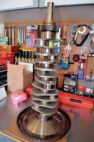
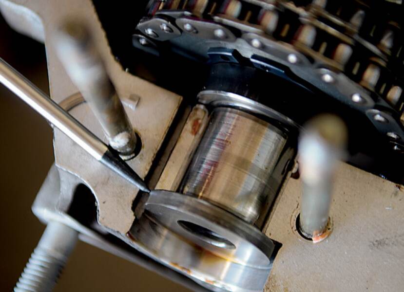
In Part 1 we noted that Steven was really looking to equalize the playing field against the more modern iron running at his local race track, and that he was planning to fully utilize some of their own bag of tricks to do so. Peter’s kindhearted gift started his engine build in the right direction, because these rods require a GT3 crankshaft to work with them. The GT3 crank is much heavier duty than the OEM 993 crank, main bearing sizes are equivalent, it has larger counter balances and oiling capabilities, and its connecting rod journals are wider (22 mm vs. 19 mm) with a smaller diameter (53 mm vs. 55 mm). By reducing the mass of the overall con-rod journal size for the design of the GT3 crankshaft, this facilitated the ability to sustain the higher rpm.
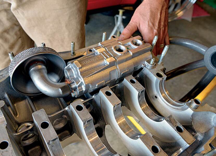
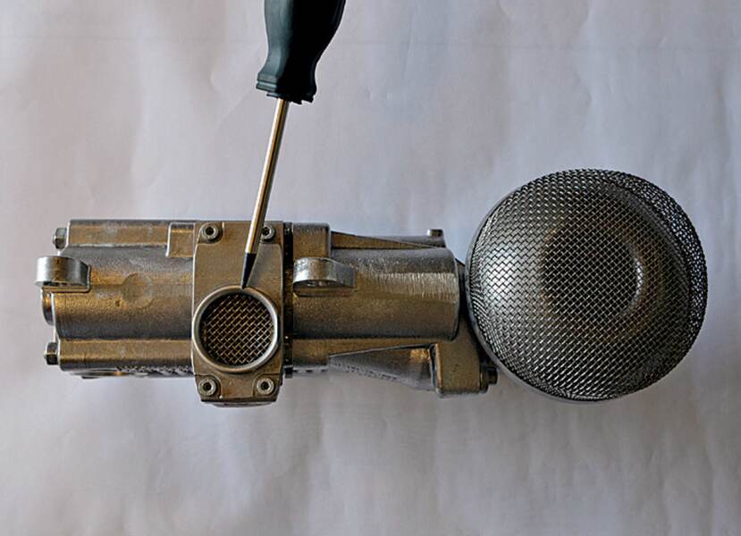
Building a strong, reliable foundation is the basis for every build project, and an internal combustion engine is no different. Again, it is a very slippery slope, because it is highly recommended that one also utilize a GT3 oil pump to keep things in check and lubricated properly. In addition, new GT3 main bearings, new GT3 rod bearings, and new GT3 rod bolts were also required (and now is a very good time to read the sidebar, “How good are you at sleuthing out deals on Porsche parts?”). Using a full GT3 bottom end in his build will ensure strength and reliability as well the ability to run to a higher maximum rpm than the 993 crankshaft.
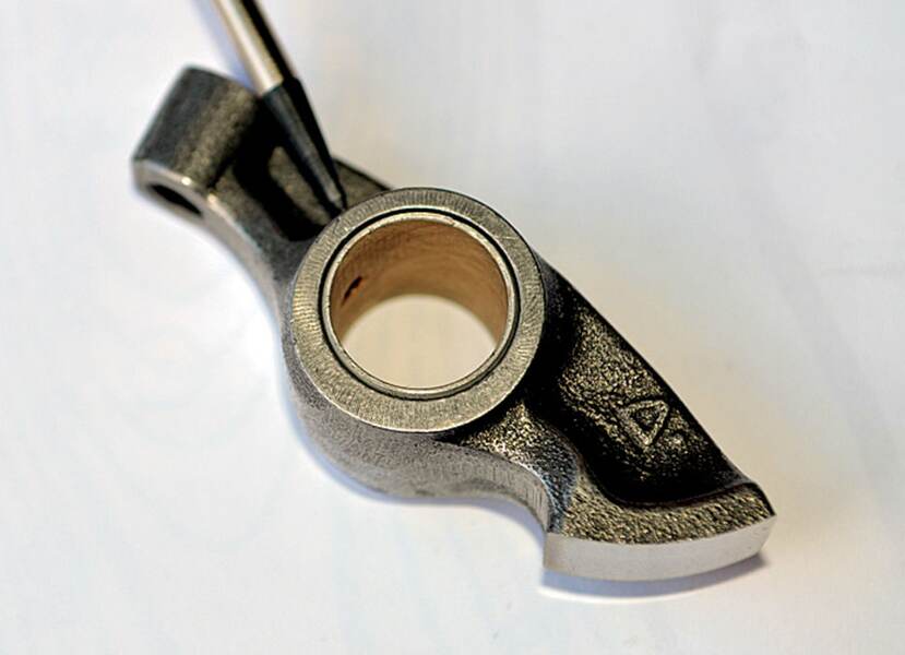
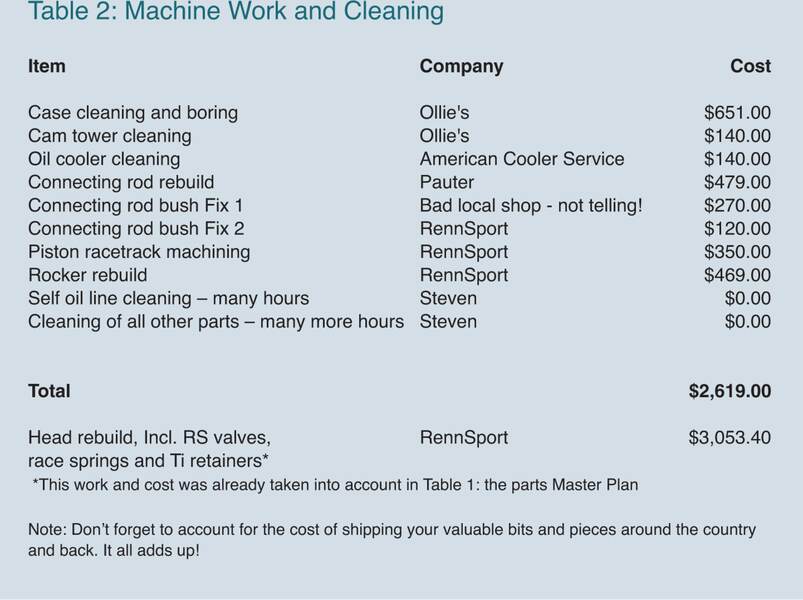
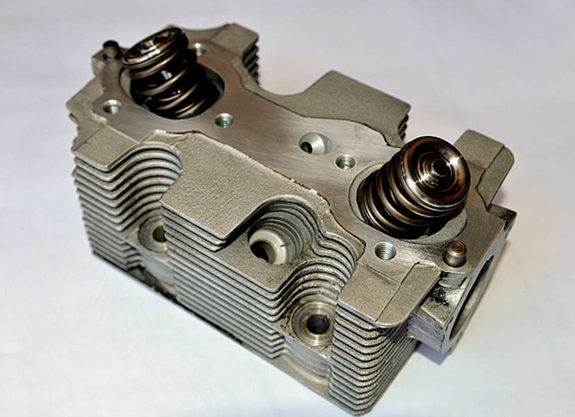
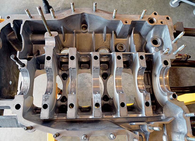
While Steven contemplated his next “power move,” he figured that he would send some of his parts for professional cleaning and refurbishing. The engine case and cam towers were shipped to Ollie’s Engineering in Lake Havasu City, Arizona, for a thorough cleaning; the heads and rockers were shipped to Steve Weiner at Rennsport in Portland, Oregon, for porting, machine work, and full rebuild with larger RS spec valves (51.5 mm for intake, and 43.5 mm for exhaust (stock: 49.5/42.5 mm), titanium retainers and racing valve springs; and the used GT3 connecting rods were sent to Pauter in Chula Vista, California, for a full refurbishing (small end re-bushing and big end trueing). Also, Steven sent his oil cooler for cleaning to American Cooler Service in Arlington, Texas, and took on the tedious task of cleaning his oil lines out himself with fishing line and gun cloth—tedious work!
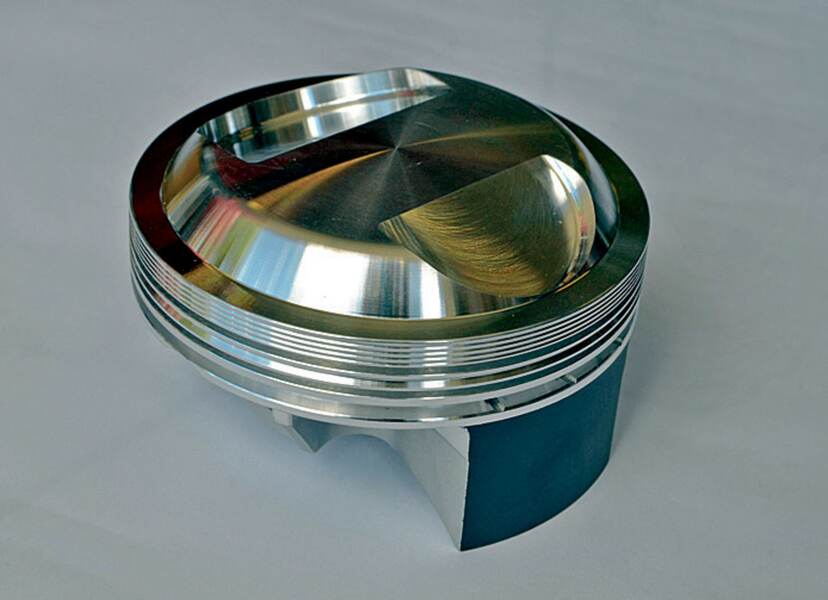
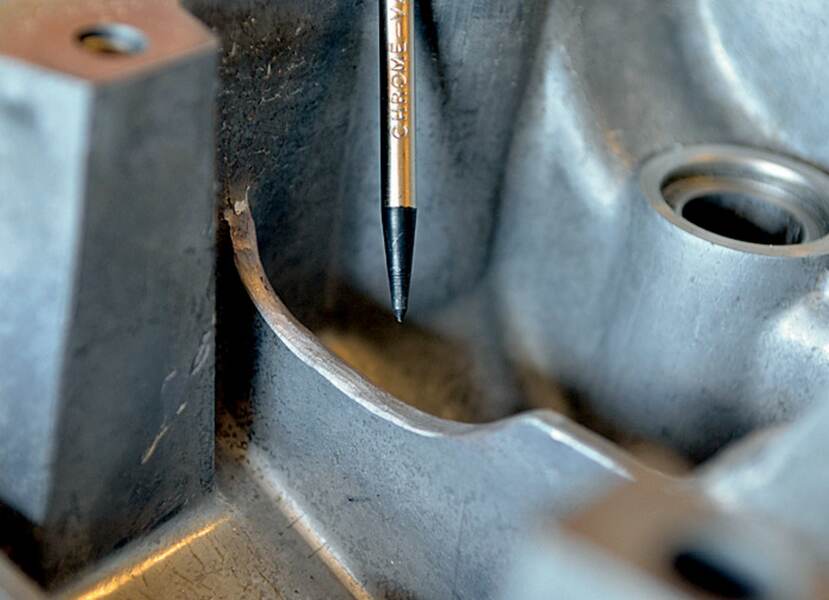
It was clear at this point that Steven was fully committed (literally!) to building an “epic” normally aspirated air-cooled flat six, so it was time to use the oldest trick in the book: “There is no substitute for cubic inches.” Steven ordered up a custom set of JE forged side relief (FSR) pistons with an 11.5:1 compression ratio, and a matching set of LN Engineering custom billet cylinders. Steven worked with Charles Navarro at LN Engineering on the piston design, which carefully took into consideration the camshaft options and valve sizes. At the same time as he ordered his new pistons and cylinders, he ordered additional boring of his engine case cylinder opening to 109 mm to allow for the much larger 105 mm bore pistons and cylinders. Note that the combination of this 105 mm bore and the GT3 stroke 76.4 mm (which as we know is the same as the factory 993) works out to be a whopping 4.0L—okay, 3.969L to be more precise. This 993 is gonna fly!
But Steven wasn’t quite finished yet: The next order of business was camshaft choice. There are many things to consider here for cam lobe profiles: duration, overlap, lift, lifter type, lobe separation angle, as well as how to consider such specifications for one’s specific purpose and method of fuel delivery.
Solid lifters will be used to allow both a more aggressive lobe and increased rpm. Also, Steven would eventually like to move to individual throttle bodies (ITBs) from the Bosch OEM fuel-injection system, but after this expensive rebuild will have to wait for a couple of years. He decided on a camshaft that would allow him to upgrade to ITBs later without the need to dig into the engine again, choosing the Dougherty Racing DC80/RSR cam. This is a very aggressive cam that will not work at all with the stock Bosch ECU, and it will not allow an engine with the Bosch OEM fuel-injection system to idle at stock levels of 650 to 750 rpm. A standalone ECU will be utilized (and, of course, will be covered fully in our planned engine tuning article), but it remains to be hoped the engine will idle at 1100-1200 rpm….not ideal, but not the end of the world either, especially for a dedicated track car.
Now that all of the existing keeper parts from Steven’s original engine have been cleaned and organized, and the new OEM and exotic parts have arrived, you would think it is time to build this monster. Well, not so fast! Sure, there will be some partial assembly, but this is a mock assembly that’s necessary for confirming the new engine’s internal measurements and machine work before the actual final sealing and torquing up can be completed.
Let us go through these checks now. A standard OEM rebuild has a long list of technical measurements that should be carefully checked and re-checked (see your workshop manual for full details). However, Steven has many new performance parts that will be added into the mix. The near re-engineering of his humble 3.6L requires him to check all of the machine work and custom parts to ensure they will all work in harmony and have the correct technical tolerances (either OEM or by the aftermarket manufacturer).

He begins by checking the case bore machining with a bore gauge. Next he can check with an outside micrometer the specs of the new GT3 crank’s main and rod journals, as well as the new GT3 bearing halves. He needs also to check the work done by the company that performed the connecting rod refurbishing. The big end is measured with a bore gauge before and after the new rod bearings are inserted into position. The small end had new bushings installed to match the piston pins.
As it turned out, the connecting rod small-end bushings were incorrectly sized too small (they would not fit on the piston pins)—due not to a machining error but to a miscommunication of the specification required. (Those damn GT3 connecting rods!)
No problem. Steven sent them out locally to be re-done. But, wait—problem! The local company fluffed it up (lesson learned: use reputable Excellence advertisers!), causing variations in connecting rod length by up to 0.2 mm. (Those damn GT3 connecting rods!) Anyway, Steven solved the problem when he required additional machining for the ultra-precise “deck height” specification.

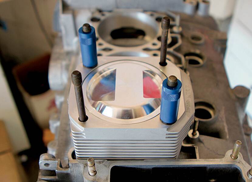
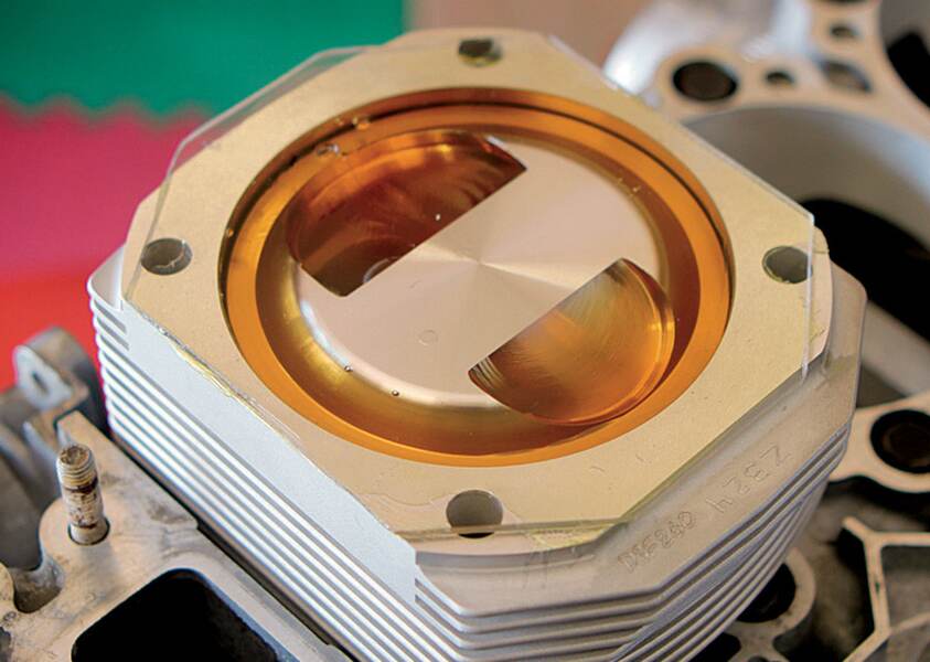
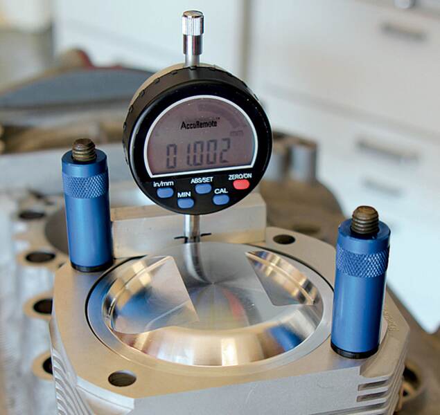
In order to check that the new pistons, con rods, and crank will “play” together nicely, one needs to check the deck height, which is defined as “the minimum depth that the top edge of the piston sits in the cylinder at top dead center (TDC) with respect to the machine top of the cylinder head.” To do this Steven had to “mock” build the engine, installing crank, con rods, and pistons and cylinders. (Note: Some of the contoured piston head will extend out of the cylinder and into the head for compression and for engineered airflow/turbulence, but the edge, called the “race track” of the piston, must sit below.) A typical value for deck height is minus 0.8 to minus 1.0 mm (a positive number means the piston edge is coming out of the cylinder—not good!).
If the piston and connecting rods are fixed to the crank, how does one adjust the deck height? Well, one could custom machine the small-end bushings of those damn GT3 connecting rods to specific lengths, but this would result in minute differences in engine stroke. The better way on a 993 engine is to precisely match the connecting rod lengths and machine the “race track” of the piston crown. Steven had Steve Weiner at Rennsport correct those damn GT3 connecting rod small-end bushings for equal lengths (to 0.01 mm) and machine the race tracks of his pistons to the precise deck height of minus 0.8mm, utilizing Steven’s precise measurements for each cylinder. Interestingly, the deck height for old 911 engines can be adjusted by adding or subtracting shims at the bottom of the cylinder where it meets the case.
Now, and only now, are we ready to safely put this engine back together. Unfortunately, we are out of time, but we promise you in the next article to take you through the assembly of Steven’s custom 4.0L powerplant, from installing the GT3 crankshaft all the way to bolting the intake plenum back on.

